I'm playing with a Netduino microcontroller with a view to making a digital readout for my lathe (using a linear encoder from machine-dro.co.uk). So I experimented with a couple of rotary controllers I had lying around which were pretty flaky. After quite a bit of googling and poking around, I found the following code gave me the most satisfactory results, so I thought I'd post it in case anybody else found it handy (feel free to suggest improvements):
The steam engine is finally finished! I was a bit lazy about taking photos so there are a few steps I didn't capture (most notably creating the piston/piston rod/crosshead assembly), but here's what I did...
I used an optical centre punch to punch the centre, then scribed a guideline to help me determine the bore of the cylinder.
After drilling out, I used a Glanze boring tool to bore the cylinder to its final diameter, using a telescopic bore gauge to check as I went along. The boring tool gave a lovely finish, and I polished it after boring it using a piece of dowel roughly the same diameter as the cylinder covered in Tormek sharpening paste (it's what was to hand, and it gave a mirror finish).
Drilling the hole for the cylinder stud...
Drilling the steam ports at an angle. Some people recommend drilling them straight and not all the way through, then drilling a hole from the ends of the cylinder to connect it up (there's an excellent series of posts by 'Bogs' on rebuilding a badly-made twin oscillator that's well worth perusing. It's possible that I've made every mistake he describes, but I try not to think about it).
Turning the cylinder covers. The phosphor bronze was an absolute pig to turn.
I should have left myself a bigger spigot, but I got away with it.
The cover is a nice fit - stays in when you turn it upside down too!
Drilling the holes for the studs that hold the whole cylinder assembly together. I decided to drill the top and bottom covers at the same time to reduce marking errors.
Again, phosphor bronze taking its toll on my drill bits...
Cylinder covers done. Very satisfying considering the covers came from a dirty lump of bronze to start with.
Unfortunately my camera wasn't to hand while I was making the piston. I reckoned it was important to ensure that the piston and crosshead were exactly concentric with the piston rod. So after roughly turning the piston and crosshead to size, I tapped them and attached them to the piston rod, then finished them off while holding the piston rod in a collet. It all went swimmingly until my cutter snagged the crosshead and bent the end of the piston rod. If I feel inclined, I may make a new piston rod assembly later on (especially since I cocked up drilling through the crosshead), but I decided to press ahead with what I had for now.
Putting it all together. Amazingly, it all fitted!
Loosely assembled....
Here it is compared to a casting (I bought a second casting in case I messed up, so now I have to make another one!).
Finally I drilled holes for the cylinder lagging screws. And here a word of warning! If you follow the measurements on the plan, you're very likely to end up with the screws overlapping the edge! I was so annoyed! I'll have to find some 7BA screws with a smaller head somewhere, but these will have to do for now.
So here's the finished engine. For such a small thing, it took an enormous amount of time to complete, but I learned a lot in the process, and I have the courage now to tackle something a little more ambitious.
You can see it running (too fast) on compressed air here:
I went to the London Model Engineering Exhibition, and spent an awful lot of money on taps, dies, reamers, knurlers, optical centre punches, marking gauges, indexed tool bits and various other odds and ends. The upshot of this is that I was able to make some progress on my engine. I attached the flywheel with three 8BA grub screws in the pulley instead of a bloody great hole through the main flywheel, I was also able to knurl the adjusting knob. Quick lick of stuart green paint, and it all looks better.
I really don't like the flat bit on the top of the casting, so I decided to make an oil cup (inspired by John R Bentley in his astonishing post here). First I faced off a bit of brass and drilled a small hole...
...then I tapped the tip (5BA) and did some shaping...
Tidied up the end
Parted off....
Screwed the oil cup into an offcut of brass with a 5BA threaded hole, then drilled out the cup. And that's it!
Removed some paint, and drilled a hole - yes, it's a little off, isn't it. Drilling holes is really where the difficulty in all this stuff is...
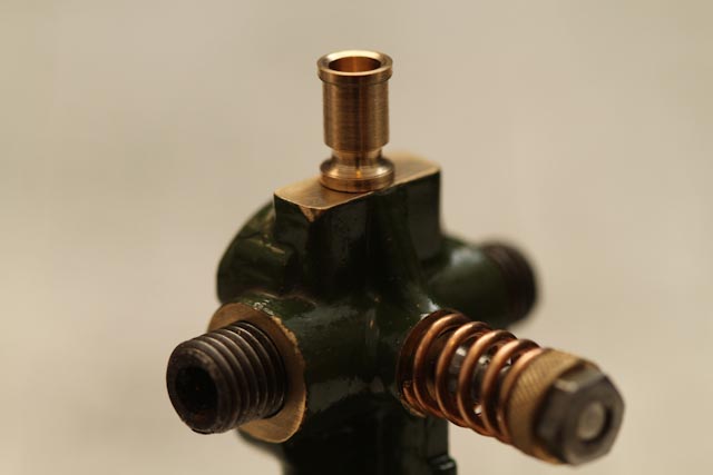
Finally screwed in the oil cup. It looks a bit eccentric but when the cylinder's attached I think it'll balance out.